Individual Assignment
✅
Design, build, and connect wired or wireless node(s) with network or bus addresses and local input &/or output device(s).
Group Assignment
✅
Send a message between two projects
Table of Contents
Hero Shot
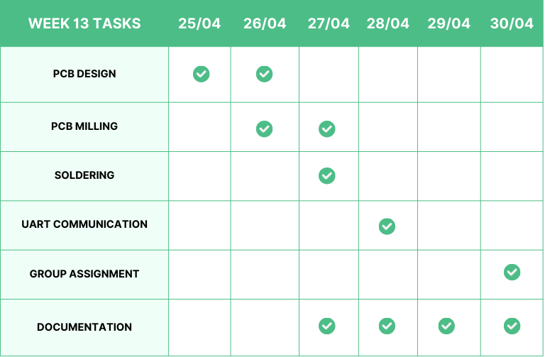
Week 13 Work Plan
IDEA
📌
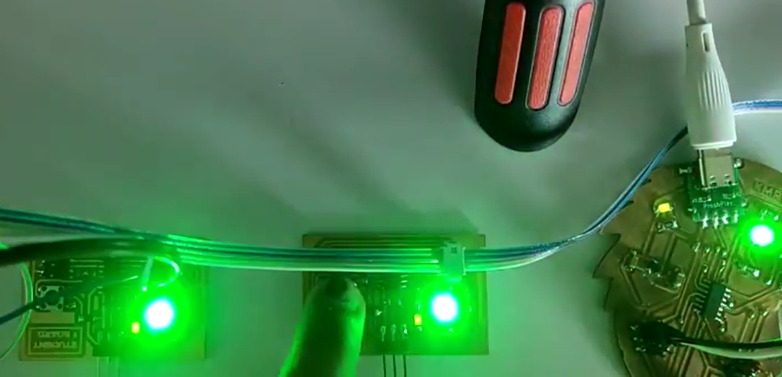
The idea for this is to create a short project. The project involves three boards that communicate with each other. Each board will have an RGB LED and a push button, which will be connected to each other using UART. Each push button will receive a specific color value, and upon pressing the button on the first board, all the LEDs on the board will illuminate with the assigned color. Similarly, other buttons will cause the LEDs on the other board to glow in accordance with the pressed button's assigned color.
Creating the Plan
➡️
Step 1: Brainstorm about the idea to implement in this week.
➡️
Step 2: Learn the basic of UART Communication.
➡️
Step 3: Design and fabricate the student boards.
➡️
Step 4: Programming and debugging.
UART
UART (Universal Asynchronous Receiver/Transmitter) is a commonly used serial communication protocol in electronics and embedded systems. It facilitates the transmission and reception of data between devices using two wires: one for transmitting data (TX) and one for receiving data (RX).
⬇️
Follow the link below to learn more about the basic UART communication protocol.
Basics of UART Communication
UART is used to connect modules like GPS, Bluetooth, and RFID card readers to the Raspberry Pi, Arduino, and other microcontrollers. Learn how it works with this easy to understand tutorial.
 https://www.circuitbasics.com/basics-uart-communication/
➡️
Asynchronous Communication: UART is asynchronous, meaning there is no separate clock signal shared between the sender and receiver. Instead, both devices agree on a common baud rate, which defines the speed of data transmission.
➡️
Serial Transmission: UART transmits data serially, one bit at a time, over two wires: one for transmitting data (TX) and one for receiving data (RX). It's a point-to-point communication protocol, meaning it typically involves communication between two devices.
➡️
Start and Stop Bits: Each data byte sent via UART is framed by start and stop bits. The start bit indicates the beginning of a data byte, while the stop bit marks its end. This framing helps the receiver synchronize with the incoming data.
➡️
Data Format: UART supports various data formats, including the number of data bits per frame (typically 7 or 8 bits), parity bit for error detection (optional), and the number of stop bits (usually 1 or 2).
➡️
Baud Rate: The baud rate determines the speed of data transmission. Both the transmitting and receiving devices must operate at the same baud rate for successful communication. Common baud rates include 9600, 19200, 38400, 115200, etc.
➡️
Half-Duplex Communication: UART supports half-duplex communication, meaning data can be transmitted and received, but not simultaneously. Devices can alternate between sending and receiving data.
➡️
Hardware Implementation: UART functionality is often implemented using dedicated hardware peripherals within microcontrollers or UART ICs. These peripherals handle the low-level details of data transmission and reception, allowing software to interact with UART data via registers or APIs.
➡️
Application: UART is widely used for various applications, including communication between microcontrollers, sensors, actuators, displays, and other peripheral devices. It's a simple and versatile protocol suitable for many embedded systems.
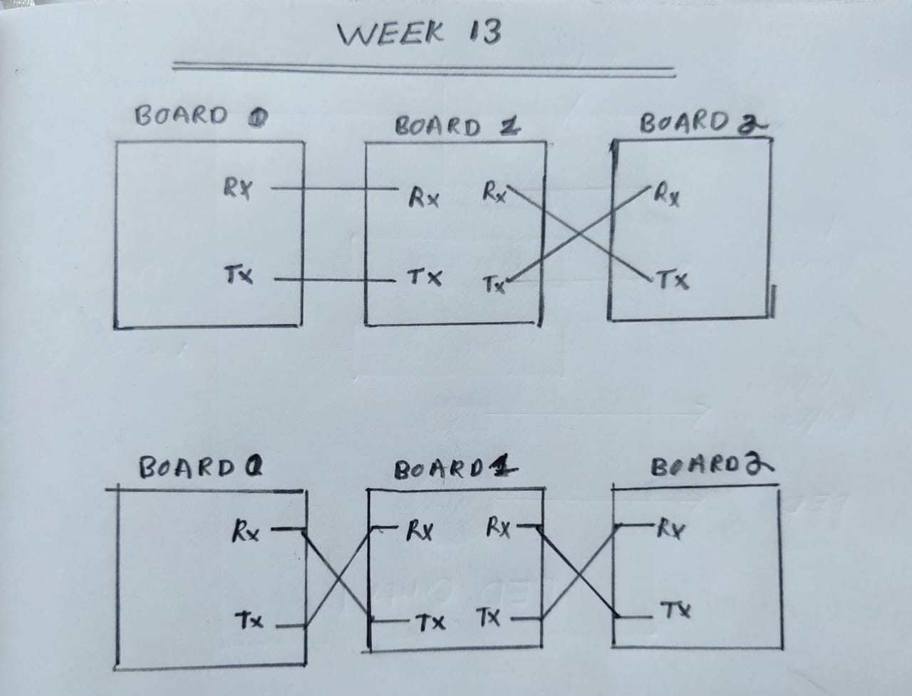
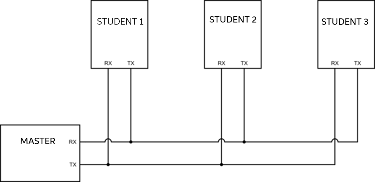
Multiple Nodes Connected Using UART
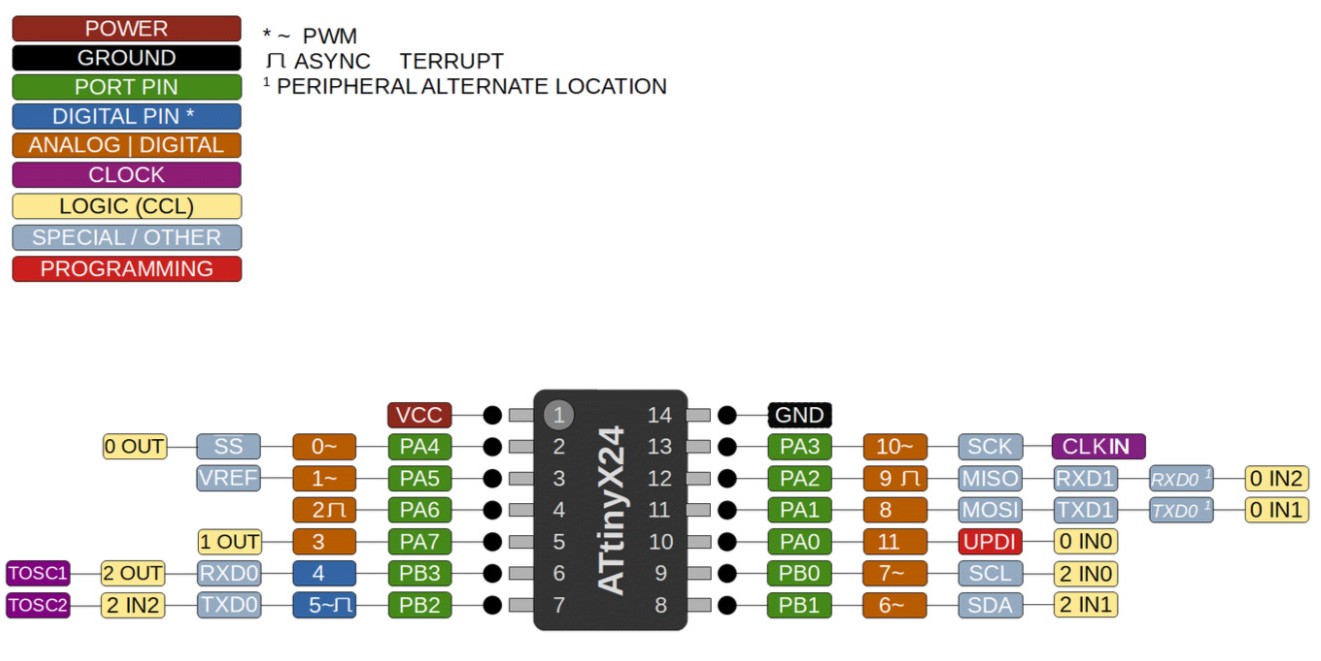
ATtiny1614
🚨
This week, I chose the ATtiny1614 as my microcontroller. To choose the microcontroller, I checked the number of pins that I needed to complete my desired task. I found that I need around 7 pins. So ATtiny412 would not be sufficient for my project, and I decided to choose ATtiny1614.
⬇️
The pinout of the ATtiny1614 is shown below.
Designing the Student Board
⬇️
Follow the link below to learn about PCB design.
Rayan Abdul Gafoor - Fab Academy
© 2024 Rayan Abdul Gafoor. All rights reserved. Students Agreement.
🚨
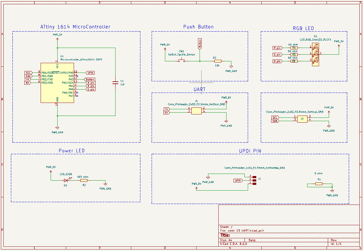
The schematic of the week 13 student board is shown below.
🚨
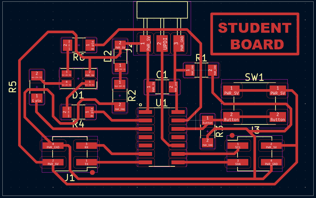
The image below illustrates the routed student board.
🚨
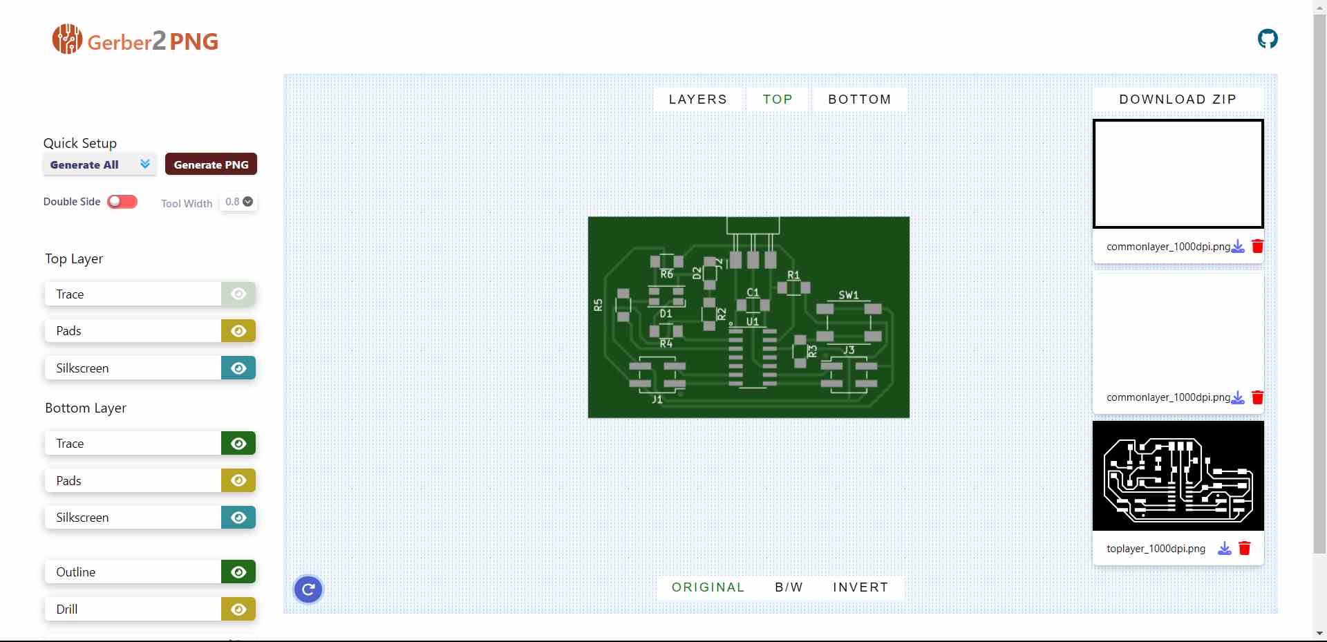
Then I exported the Gerber file and converted it into a PNG.
Gerber2Png | Fablab Kerala
 https://gerber2png.fablabkerala.in/
🚨
To learn more about how to export a Gerber file and convert it into a PNG, follow the link below.
Rayan Abdul Gafoor - Fab Academy
© 2024 Rayan Abdul Gafoor. All rights reserved. Students Agreement.
🚨
The image below illustrates the Gerber to PNG converting web app.
PCB Milling
⬇️
Follow the link below to learn how to mill PCBs using Modela.
Rayan Abdul Gafoor - Fab Academy
© 2024 Rayan Abdul Gafoor. All rights reserved. Students Agreement.
Rayan Abdul Gafoor - Fab Academy
© 2024 Rayan Abdul Gafoor. All rights reserved. Students Agreement.
🚨
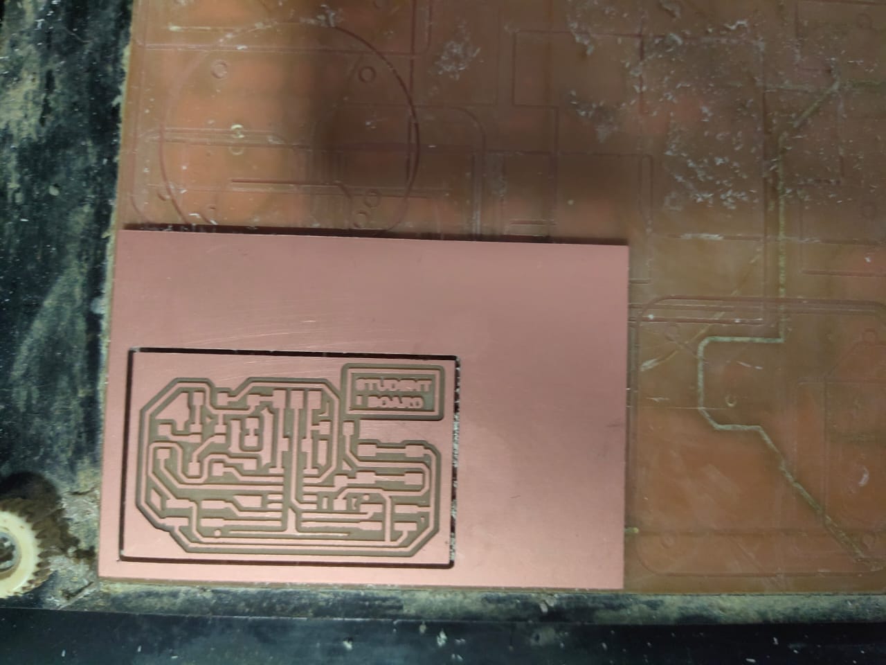
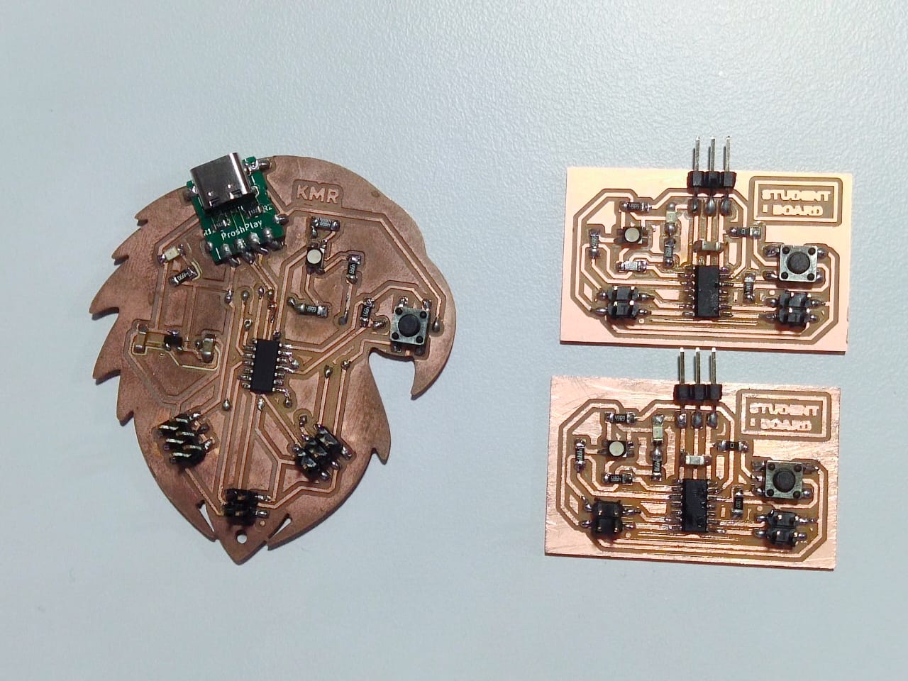
The image below depicts the milled student board using Modela.
🚨
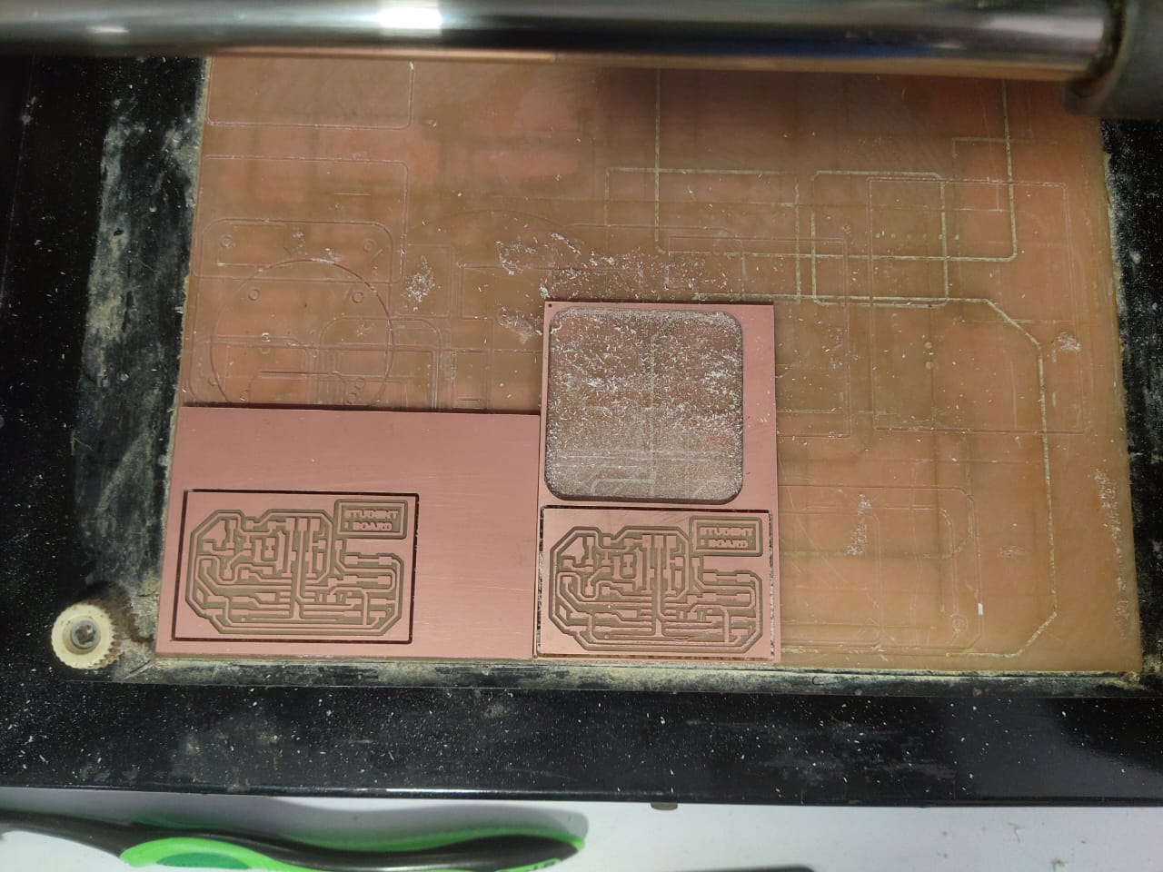
The image below depicts the milled second student board using Modela.
PCB Soldering
🚨
Follow the link below to learn more about soldering.
Rayan Abdul Gafoor - Fab Academy
© 2024 Rayan Abdul Gafoor. All rights reserved. Students Agreement.
🚨
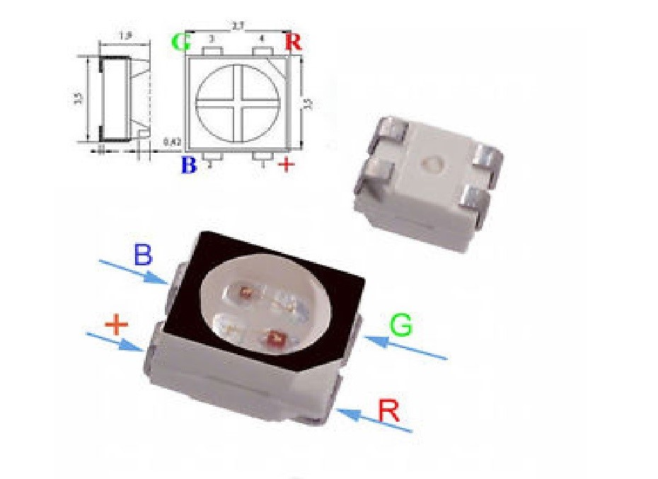
The image below illustrates the pinout of the RGB LED. In my student board, I used a RGB LED, so this pinout of the LED is very useful for me.
🚨
I collected all the components for my board, and I started soldering my board. As usual, I did my soldering, used the multimeter continuity mode to debug the traces, and utilised the microscope to probe further.
Bootloader
🚨
To use the ATtiny1614, I need to programme the chip. I chose the QT development board to programme the ATtiny1614 using UPDI.
🚨
Follow the link below to learn more about programming the ATtiny 1614 using the QT development board.
Rayan Abdul Gafoor - Fab Academy
© 2024 Rayan Abdul Gafoor. All rights reserved. Students Agreement.
🚨
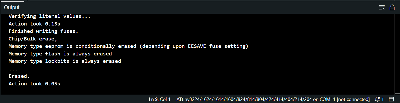
After successfully burning the bootloader, the output is shown below.
Programming the Eagle Board and the Two Student Board
🚨
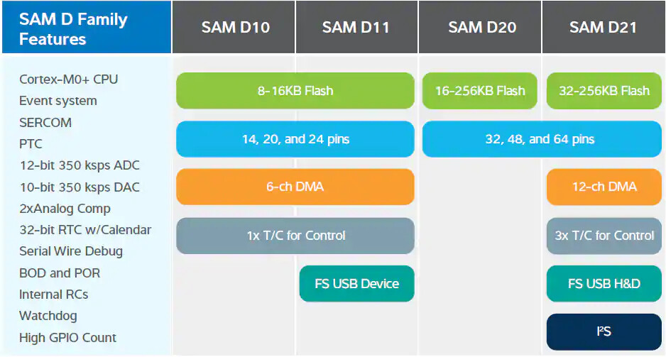
Before programming the Eagle board, check the memory capacity of the chip that you are using. The image shown below illustrates the memory capacity of the SAM-D family.
🚨
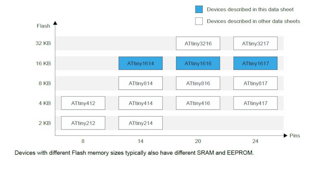
The image shown below illustrates the memory capacity of the ATtiny family.
Eagle Board Code
// Eagle Board [Board 0] CODE

// Define pin numbers for button and RGB LED
#define button 4
#define redPin 5
#define greenPin 8
#define bluePin 9

// Variable to store incoming message
char message;

void setup() {
  // Initialize serial communication at a baud rate of 9600
  Serial1.begin(9600);

  // Set button pin as input
  pinMode(button, INPUT);

  // Set RGB LED pins as output
  pinMode(redPin, OUTPUT);
  pinMode(greenPin, OUTPUT);
  pinMode(bluePin, OUTPUT);

  // Turn off RGB LED initially by setting all colors to HIGH (assuming common anode RGB LED)
  digitalWrite(redPin, HIGH);
  digitalWrite(greenPin, HIGH);
  digitalWrite(bluePin, HIGH);
}

void loop() {
  // Check if there is any data available to read from the serial port
  if (Serial1.available()) {
    // Read the incoming message
    message = Serial1.read();

    // Check the received message and set the LED color accordingly
    if (message == '0') {
      // Set LED color to blue
      analogWrite(redPin, 255);
      analogWrite(greenPin, 255);
      analogWrite(bluePin, 0);
    }
    if (message == '1') {
      // Set LED color to green
      analogWrite(redPin, 255);
      analogWrite(greenPin, 0);
      analogWrite(bluePin, 255);
    }
    if (message == '2') {
      // Set LED color to red
      analogWrite(redPin, 0);
      analogWrite(greenPin, 255);
      analogWrite(bluePin, 255);
    }
  }

  // Check if the button is pressed
  if (digitalRead(button) == 1) {
    // Send '0' character over serial when button is pressed
    Serial1.write('0');

    // Set LED color to blue
    analogWrite(redPin, 255);
    analogWrite(greenPin, 255);
    analogWrite(bluePin, 0);
  }

  // Small delay to debounce the button and to prevent spamming the serial port
  delay(20);
}
Explanation of the Code
- Pin Definitions:💠
button,redPin,greenPin, andbluePinare defined with pin numbers for easier reference.
- Setup Function:💠Initializes serial communication with a baud rate of 9600.💠Sets the button pin as input and RGB LED pins as outputs.💠Initializes the RGB LED to be off (assuming a common anode configuration where HIGH turns the LED off).
- Main Loop:💠Checks if there is data available on the serial port.💠Reads the incoming character and changes the LED color based on the value of
message:- '0' sets the LED to blue.
- '1' sets the LED to green.
- '2' sets the LED to red.
💠Checks if the button is pressed:- Sends a '0' character over the serial port.
- Sets the LED to blue.
💠Includes a small delay to debounce the button and to prevent rapid serial writes.
Student Board 1 Code
// Board 1 CODE

// Define pin numbers for button and RGB LED
#define button 9
#define redPin 0
#define greenPin 1
#define bluePin 10

// Variable to store incoming message
char message;

void setup() {
  // Start serial communication at a baud rate of 9600
  Serial.begin(9600);

  // Set button pin as input
  pinMode(button, INPUT);

  // Set RGB LED pins as output
  pinMode(redPin, OUTPUT);
  pinMode(greenPin, OUTPUT);
  pinMode(bluePin, OUTPUT);

  // Turn off RGB LED initially by setting all colors to HIGH (assuming common anode RGB LED)
  digitalWrite(redPin, HIGH);
  digitalWrite(greenPin, HIGH);
  digitalWrite(bluePin, HIGH);
}

void loop() {
  // Check if there is any data available to read from the serial port
  if (Serial.available()) {
    // Read the incoming message
    message = Serial.read();

    // Check the received message and set the LED color accordingly
    if (message == '0') {
      // Send '0' character back over serial
      Serial.write('0');
      // Set LED color to blue
      analogWrite(redPin, 255);
      analogWrite(greenPin, 255);
      analogWrite(bluePin, 0);
    }
    if (message == '1') {
      // Set LED color to green
      analogWrite(redPin, 255);
      analogWrite(greenPin, 0);
      analogWrite(bluePin, 255);
    }
    if (message == '2') {
      // Send '2' character back over serial
      Serial.write('2');
      // Set LED color to red
      analogWrite(redPin, 0);
      analogWrite(greenPin, 255);
      analogWrite(bluePin, 255);
    }
  }

  // Check if the button is pressed
  if (digitalRead(button) == 1) {
    // Send '1' character over serial when button is pressed
    Serial.write('1');
    // Set LED color to green
    analogWrite(redPin, 255);
    analogWrite(greenPin, 0);
    analogWrite(bluePin, 255);
  }

  // Small delay to debounce the button and to prevent spamming the serial port
  delay(20);
}
Explanation of the Code
- Pin Definitions:💠
button,redPin,greenPin, andbluePinare defined with pin numbers for easier reference.
- Setup Function:💠Initializes serial communication with a baud rate of 9600.💠Sets the button pin as input and RGB LED pins as outputs.💠Initializes the RGB LED to be off (assuming a common anode configuration where HIGH turns the LED off).
- Main Loop:💠Checks if there is data available on the serial port.💠Reads the incoming character and changes the LED color based on the value of
message:- '0' sends a '0' character back and sets the LED to blue.
- '1' sets the LED to green.
- '2' sends a '2' character back and sets the LED to red.
💠Checks if the button is pressed:- Sends a '1' character over the serial port.
- Sets the LED to green.
💠Includes a small delay to debounce the button and to prevent rapid serial writes.
Student Board 2 Code
// Board 2 CODE

// Define pin numbers for button and RGB LED
#define button 9
#define redPin 0
#define greenPin 1
#define bluePin 10

// Variable to store incoming message
char message;

void setup() {
  // Start serial communication at a baud rate of 9600
  Serial.begin(9600);

  // Set button pin as input
  pinMode(button, INPUT);

  // Set RGB LED pins as output
  pinMode(redPin, OUTPUT);
  pinMode(greenPin, OUTPUT);
  pinMode(bluePin, OUTPUT);

  // Turn off RGB LED initially by setting all colors to HIGH (assuming common anode RGB LED)
  digitalWrite(redPin, HIGH);
  digitalWrite(greenPin, HIGH);
  digitalWrite(bluePin, HIGH);
}

void loop() {
  // Check if there is any data available to read from the serial port
  if (Serial.available()) {
    // Read the incoming message
    message = Serial.read();

    // Check the received message and set the LED color accordingly
    if (message == '0') {
      // Set LED color to blue
      analogWrite(redPin, 255);
      analogWrite(greenPin, 255);
      analogWrite(bluePin, 0);
    }
    if (message == '1') {
      // Set LED color to green
      analogWrite(redPin, 255);
      analogWrite(greenPin, 0);
      analogWrite(bluePin, 255);
    }
    if (message == '2') {
      // Set LED color to red
      analogWrite(redPin, 0);
      analogWrite(greenPin, 255);
      analogWrite(bluePin, 255);
    }
  }

  // Check if the button is pressed
  if (digitalRead(button) == 1) {
    // Send '2' character over serial when button is pressed
    Serial.write('2');
    // Set LED color to red
    analogWrite(redPin, 0);
    analogWrite(greenPin, 255);
    analogWrite(bluePin, 255);
  }

  // Small delay to debounce the button and to prevent spamming the serial port
  delay(20);
}
Explanation of the Code
- Pin Definitions:💠
button,redPin,greenPin, andbluePinare defined with pin numbers for easier reference.
- Setup Function:💠Initializes serial communication with a baud rate of 9600.💠Sets the button pin as input and RGB LED pins as outputs.💠Initializes the RGB LED to be off (assuming a common anode configuration where HIGH turns the LED off).
- Main Loop:💠Checks if there is data available on the serial port.💠Reads the incoming character and changes the LED color based on the value of
message:- '0' sets the LED to blue.
- '1' sets the LED to green.
- '2' sets the LED to red.
💠Checks if the button is pressed:- Sends a '2' character over the serial port.
- Sets the LED to red.
💠Includes a small delay to debounce the button and to prevent rapid serial writes.
🚨
Final Result 😀
Group Assignment Page
.png)
📌
For the group documentation page click here.
Challenges
🚨
While communicating with the Eagle board, the Eagle board is not transmitting the character to the other boards, so I decided to use software serial instead of hardware serial 1 in the SAMD 11C. However, there is no software serial library for SAMD. Since SoftwareSerial was designed with AVR microcontrollers in mind, it's not directly compatible with SAMD microcontrollers. The differences in architecture, such as the availability of hardware peripherals like SERCOM (Serial Communication Interface), mean that a direct port of SoftwareSerial to SAMD isn't straightforward. Later, I tried with different jumper wires and partially solved the problem, but still, sometimes this issue arises, and I would like to solve it permanently and will be updating its cause and solution.
Reference
📌 Nadieh